Detection
and firing at moving targets has been a topic of great interest right from the
time of World War II. This majorly came in the form of anti aircraft guns used
to detect enemy aircrafts, predict their future position (or follow the
aircraft) and fire accordingly. The challenge faced by us this semester is
similar to this. We had to build a robot which shoots at static and dynamic
targets. The robot is to fire Nerf balls at retro-reflective targets at a
certain distance away. For the static target test, it is required to fire at
single static targets randomly located in the plane and limits of the target
bed. The dynamic state of the target consists of linear motion in the
horizontal direction with deceleration and acceleration at the turn around
points. Testing in this mode required us to fire at one moving and two static
targets per round, and 4 such rounds in total.
The design requirements for this project are many fold. The
robot is not to exceed dimensions of 2’x2’x2’. The power supply is supposed to
be a dedicated one and the robot is not to rely on any sort of bench supply for
power. The Nerf balls are to be dumped into the system, and not placed
strategically. The design is to be expected to track the targets actively. The
design, fabrication and testing of the robot is to be done in $350 which is
refundable. The robot is required to be really safe to operate and is to be
aesthetic in appearance. No laptop support for the final test is allowed.

Description of Subsystems
In designing our robot the majority of our major decisions
were governed by a desire to make the precision of firing as high as
possible. This took precedence over
other qualities, such as speed and firing power, and in some cases ease of
manufacture. This effort had great
influence on our decisions in designing our firing mechanism, depicted in figure 1. The firing mechanism employs a unique
approach in which the ball is "kicked" by a piece of spring steel
which has been bent back. The idea was
that if the spring was latched in to place by a physical reference before it
was allowed to swing forward, it would hold a very repeatable amount of energy,
and hit the ball in a very consistent way.
We also discussed the two other popular ways to propel the ball,
pneumatically and with a flywheel, and decided that both of these approaches
would impart a less constant amount of energy to the ball, because they will
depend on exactly how fast the wheels are spinning (which is either dependent
on the control feedback or fluctuations in the power supply) or the current
pressure in the air line. Another
positive quality of the kicking approach is the fact that it introduced zero
non internal friction to the system. We
didn't avoid friction because it is inefficient, we avoided friction because it
introduces randomness. We didn't have to
rely on the seal between the ball and a barrel being identical in every shot,
or the friction between the ball and a wheel being identical in every
shot. We did not rely on friction to add
energy and there was a negligible possibility of friction subtracting
energy. We designed our ball rest in
such a way that the ball leaves contact with the robot instantaneously with no
rolling or sliding, thereby minimizing the randomizing role that friction would
play.

Figure 1: Entire firing mechanism with actuation
This choice of launching mechanism introduced an important
difficulty. We immediately knew that the
amount of torque it would take to pull back the spring would be large. After evaluating many different options we
decided on using an electric power drill to supply this torque. This simplified the setup fairly considerably
by providing enough raw torque to make any extra gear reduction
unnecessary. We simply made an arm with
a shaft on it that the drill could grip that would pull back the spring until
it caught in the latch. The amount of
power this provided was very large. We
started out with a stiffer spring that had dramatically more firing power, and
the drill was still easily capable of pulling back this larger torque spring in
a fraction of a second.
After testing with the power drill we needed to find a way to
control it with the micro controller. We
originally had planned to try to drive it down and then back up, but found that
the safety features on the device made it difficult to quickly switch
directions. The solution we found in the
end was much more elegant anyway. We
connected the end of our loading arm to a spring which simply back drives the
drill when it is not running. The torque
the drill provides is easily large enough to overcome this weak spring, and the
instant it is turned off it gets neatly pulled back in to the starting
position, out of the way of the launching spring. This innovation allowed us to control the
drill with a much simpler single relay setup.
We tied down the power switch on the drill and then used a simple relay
to effectively plug and unplug its power cord every time we needed to cock the
firing spring.

Figure2: Latch that holds the ruler loaded
The two remaining components to the firing mechanism are the
spring latch and ball feeding mechanism.
The spring latch was given a torsional spring that holds it up and
allows the firing spring to click in to place.
We then actuated this latch with a servo connected by a string. This way when the latch needed to pull away
to allow the spring to click in it could do so without needing to wait for the
servo to move out of the way. figure 2. This ended up to be a critical feature,
because the servo moved much slower than we expected, and the power drill moved
much faster than we expected. The power
drill draws a very large amount of current when it stalls at the end of its
stroke, so waiting for the servo to move to its extremes might have been a long
enough pause to actually burn out the motor in it.
The ball feeding mechanism figure 3 consists of a simple gate that allows one ball to pass
and roll in to the rest every time it rotates 90 degrees and back. Above this gate was a tube that allowed all
six balls to queue up. At the top of the
tube was a flat corral area that
funneled the balls into it (figure 4).
In order to proven the balls from jamming against each other and not
feeding in to the tube a simple wheel was added at the height of the centers of
the balls. This wheel was placed so that
any time two balls would have bumped in to each other to span the width of the
funneling area and stopped the balls behind them from moving forward, one of
them would be rotated back out of the way to the back of the line, allowing the
others to move.

Figure3: Ball loading mechanism
The important feature of this technique was the direction the
wheel rotates in. Any attempt to push
the balls forward would cause them to jam even tighter, but by pushing the
jammed balls back uphill (where there was space for them to move) they would be
moved easily. This mechanism proved to
be very capable, occasionally clearing jams involving 5 of the 6 balls.
Another area in which our strive for precision played a large
role was in the design of our vertical and horizontal actuation. Since we wanted to very carefully control our
shooting power to be constant, we elected to simply rotate our shooting
mechanism to point in the appropriate direction. Since we were very particular about our
accuracy, we decided that we wanted to have a precise measurement of the angle
in both of these dimensions and feed this back to our micro controller for
control. For this reason we shied away
from using servos or stepper motors for these dimensions. We got an academic discount on some very nice
1024 positions per rotation absolute position encoders which we used in both
our axes. This meant that we would have
an accuracy of around .3 degrees. In the
end one of these broke and we replaced it with a simple potentiometer. We were surprised to see that this seemed to
work just as well.

Figure4: Aluminum
trough that loads balls and avoids ball clogs
To actuate these two axes we originally planned on using a
horizontal timing belt and a vertical lead screw. We replaced the timing belt with a bike chain
early on because it was easier to source, and then ended up having chronic
problems with it. Keeping it properly
tensioned was a constant ordeal. In the
end we replaced this with a four bar linkage between the drive motor and the
thrust bearing that the whole platform was mounted on (figure 5). For the vertical axis we discarded the lead
screw due to speed concerns (as well as ease of sourcing) in favor of a simple
spool and cable. Figure 6 The
cable pulls on a bar that is tied to an axle on which the launching mechanism
is mounted.

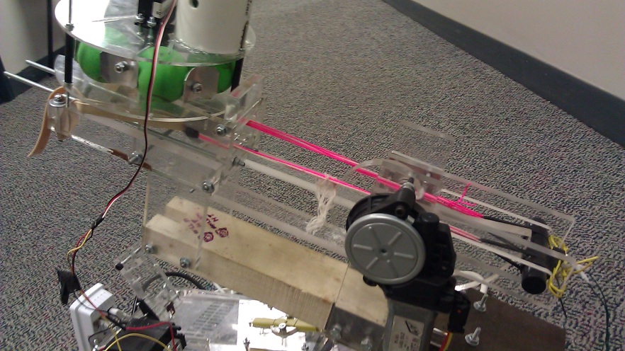
Figure5: Picture
showing the four bar linkage to actuate the turntable and a pot for position
feedback
The final important decision necessary was what hardware to
use for our vision system. As discussed,
one of the requirements was that no personal computers could be used for image
processing. Since we wanted to follow
this rule we quickly narrowed our choices down to either the CMU cam or the
Wiimote IR sensor. These were the two
options that would seem to work with the micro controller that we had decided
to use and were already comfortable with (arduino). Both of these options did the image
processing on board. The Wiimote sensor
seemed to be more difficult to set up, requiring somewhat intense disassembly
and resoldering, but seemed also to have better qualities. In particular, the frame rate and resolution
seemed to be much better on this device than the CMU cam. The price was also much better, although we
would have been much more likely to go with the CMU cam if we had known that we
would get a steep discount on it. By the
time the pricing on the CMU cam was listed we were close enough to having the
Wiimote sensor working that we decided not to make a change.

Figure6: Pitch
actuation using a spool and some thread
Team Members and Responsibility
Ben Strassmann - Camera and electronics hardware and software;
Nishant Kelkar -Wiring, ball management
Sahil Girish - Manufacturing and Design
Steven Christensen - Manufacturing and Design
Video


