The goal of this project is to build a mechatronic device capable of shooting projectiles (Nerf ballistic balls) and striking static and dynamic targets continuously. To achieve this goal, since all of our group members are mechanical engineers, our design of the shooting mechanism is more focused on using mechanical structures. Basically, we use rubber bands to generate elastic potential energy for shooting and use a cam to tighten and loosen the rubber bands. To realize the tracking of targets in different positions, we need to aim our robot to different targets accordingly. We designed two mechanical subsystems to get pitch and yaw freedoms. Specifically, we designed a four-bar linkage for pitch and a square turntable for yaw. Details can be found in the descriptions of overall system and subsystems.
For sensing, we used an IP camera to grab RGB information of the target board and detect different targets using RGB information. The microcontrollor we use is CompactRIO, which is unique among all groups this year. And we used LabView for control system programming.
2. Team members and responsibility
Haiyue Li (Team leader): Electrical control system design and realization, assistance in design and assembling, testing, final report.
Bowei Tang: Mechanical structure design, assistance in assembling, testing, final report.
Xiaowei Zhu: Manufacturing and assembling, sensing, testing, webpage.
3. Labeled pictures of the overall system with description

Fig.1 Overall System

Fig.2 Overall Control System
Fig.2 is an image showing the overall control system. As we can see from it, the CompactRIO microcontrollor receives information from the IP camera and control four motors accordingly(3 servo motors and 1 DC motor).
4. Pictures and descriptions of subsystems
4.1. Mechanical Subsystems
4.1.1. Aiming subsystem

Fig.3 CAD model for Aiming Subsystem(Pitch and Yaw)

Fig.4 Real Model of Aiming Subsystem
Fig.3 is the CAD model of the aiming subsystem, which contains mainly a four-bar linkage for controlling pitch and a square turntable for yaw. We also added a counterweight at behind to decrease the torque in pitch. Fig.4 is the real model we manufactured and assembled for aiming subsystem. 4.1.2. Shooting Subsystem

Fig.5 CAD Model for Shooting Subsystem
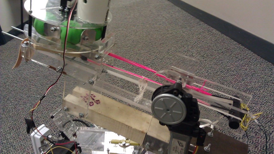
Fig.6 Real Model for Shooting Subsystem
The shooting system as we can see from Fig.5 mainly contains a cam to tighten and loosen the rubber band by pulling strings attached on the rubber band. The cam will rotate to tighten the rubber band and at the straight line position it will suddenly loosen it, which can generate enough force to shoot the ball. Fig.6 is the real model of the shooting subsystem.
4.1.3. Loading Subsystem

Fig.7 CAD Model for Loading Subsystem

Fig. 8 Real Model for Loading Subsystem
We used a long cylinder to contain balls and designed a container which separates its space into six parts as we can see from the CAD model in Fig.7. To load a ball, the servo motor will rotate 60 degrees every time to make sure one ball will fall though the hole at the bottom of the container. Fig.8 is the real model of the loading subsystem.
4.2. Electrical subsystems
4.2.1. Sensing subsystem

Fig.9 Sensing Subsystem (IP Camera)
We use an IP camera as our sensing subsystem as shown in Fig.9. The reason we choose an IP camera is that it works well with our microcontrollor CompactRIO. Also, we can get clear RGB information through this camera and have the knowledge of accurate positions of the targets.
4.2.2. Microcontrollor subsystem

Fig.10 NI CompactRIO Microcontrollor
We use NI CompactRIO Microcontrollor as our controllor and LabView as programming language. This is unique among all the groups this year. Fig.10 is an outlook image of the CompactRIO. The two modules from
the left side are all Digital I/O modules, one of which we use for common
digital input and output, the other one of which we use for generating PWM. The
third module is the Analog Input module, which we do not need for the
subsystem. The data transmission of CompactRIO is through Ethernet port.
As mentioned before, we use 3 servo motors and 1 DC motor as our subsystem of actuator. We can find them in Fig.1 which are labelled. Specifically, DC motor is used to control the rotation of the cam, and servo motor are for pitch, yaw and loading freedoms.
4.2.4. Power subsystem

Fig. 11 PC Power Supply
The PC Power Supply
can be considered as a cheap, high-power and multiple outputs transformer. It
can transform the 110v AC into DC at 3.3v, 5v and 12v. It also has protection
circuits, which make it a perfect DC power supply for our system. As the
current can reach more than 15 amps, in order to protect the servo motors, we
need regulators to limit the current.
5. Video of the system in action
Link: http://www.youtube.com/watch?v=ehOvzfmYGyY
No comments:
Post a Comment